Electrics - Page 1
LastRewiring the car following the installation of the Duratec engine
Between July 2009 and December 2010, I rewired the car again from scratch, following the installation of the new engine and engine management system.Everything in this updated section (below) is intended for my install of the DTA S80Pro, and the Ford Duratec DHE420 engine.
Although I am installing the Duratec in a front wheel drive Fiesta, much of the examples and explanations below are applicable to all installations of the Duratec engine, Front or Rear wheel drive.
I tore my original wiring loom out of the car when I first embarked on converting it for competition use, in the 1990's. Since then the car has always had my own home made engine wiring loom installed, designed and built with competition (and not road use) in mind.
 The DTA S80Pro has traction control, as well as launch control, and I need to wire in four hall-effect wheel speed sensors, two for the driven wheels, and two for the undriven wheels. It also allows for sequential injection, and sequential ignition, therefore, it requires a Camshaft sensor wiring in too. Together with the four wheel speed sensors, we're looking at some 11 sensors in the engine bay alone, as well as the power and control signals for the injectors (two banks) and the Coil On Plug packs that I'm using, so theres good reason to completely re-wire the engine bay and cockpit.
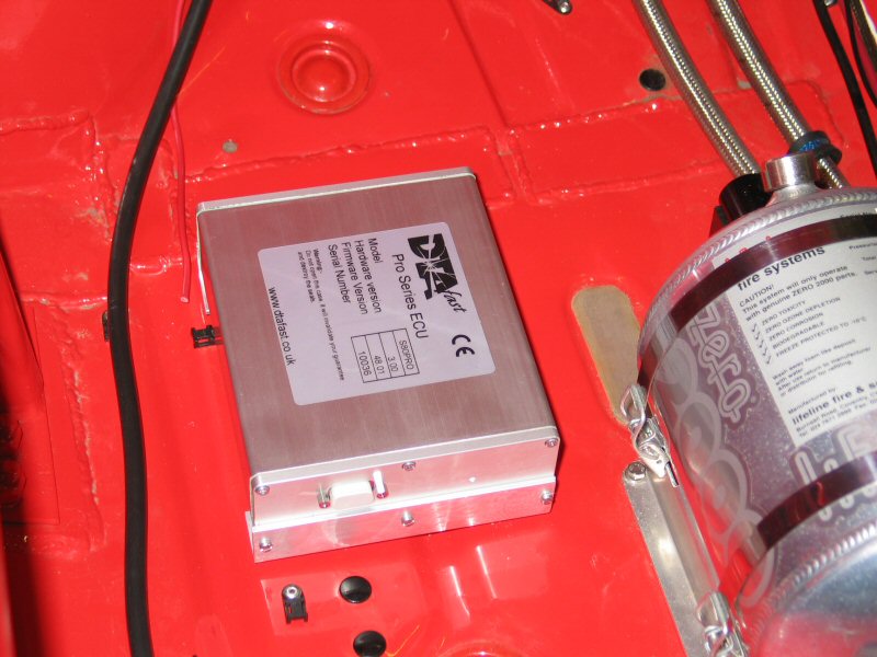
The S80Pro, as supplied by www.plays-kool.co.uk is DTA's new small format ECU, and has an overwhelming number of features. So long as I can get all the sensors wired in correctly, we should have some fun getting it setup and trying out all the features. One feature is that it has analogue outputs, and these can drive dashboard instruments directly. So the water temperature read from the engine, could be output to a temperature guage, using one of the analogue outputs, programmed accordingly. Hmm...
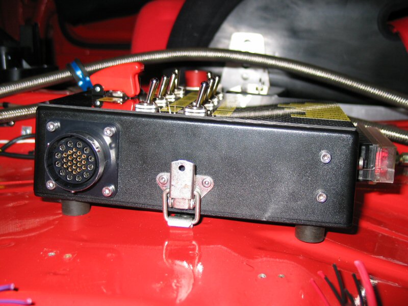
I'm using a 48-way ITT Cannon Neptune connector on the front bulkhead, to allow all the signals to pass through to the ECU from the engine bay. I'm also using shielded twisted pair cable from Radio Spares (part no. 528-2207), as well as heat shrink in various sizes, blue, clear, and adhesive lined black, to give the looms as professional a look as possible. One huge advantage of working for a major British Defence contractor, is the availability of green Nomex sleeving, if only in short lengths. The Nomex sleeve gives a flame proof finish to the loom, and looks very trick too. Nomex covers the majority of my loom, and I use adhesive heatshrink to keeps it in place. (Nomex frays very easily so must be secured by adhesive heat shrink)
I'm retaining several of the original connectors from the Duratec Fiesta ST150 donor engine wiring loom, for the magnetic 2 wire Crank and Cam sensors. Because I'm using Ford individual Coil On Plug packs, which sit atop the spark plugs, and eliminate the traditional coil pack and HT leads, I've had to source new connectors for the COPs, and these are in fact Hyabusa coil connectors, available from Lake Interconnection Systems (www.lakeics.com) for around £16 including postage and VAT (@15% in 2009).
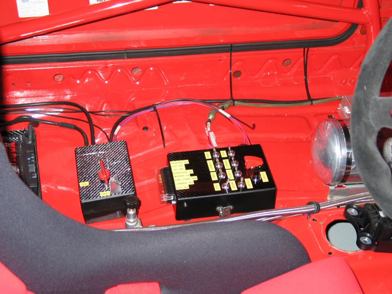
Control box
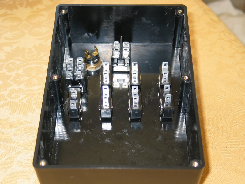
Theres many different ways to do this, but the approach I've taken in the past, is to house all the electrical control gear in a removable plastic box. The box needs to be removable to allow it to be worked on away from the car. With the addition of an ITT Canon connector, the loom can be disconnected from the box, so the box can also be removed as a security feature. No box = no power to any of the circuits, so the car is impossible to drive away.For the Duratec wiring, I located the exact same plastic black box that I used for the Zetec control box the first time I re-wired the Fiesta back in 2001, sourced from CPC. It houses the relays, fuses, and main switches for the electronics on the car. The box is made by Multicomp and is the MB6 box (part no EN81783). Only £5 but CPC add a £6 handling charge, and their website said 'next day delivery', which was a slight exageration.
- Colour: Black
- Depth, external: 220mm
- Length / Height, external: 64mm
- Material: ABS
- Width, external: 150mm
- Guide Slots: No
- Length: 220mm
- Surface finish: Matt
- Thickness, wall: 3.0mm
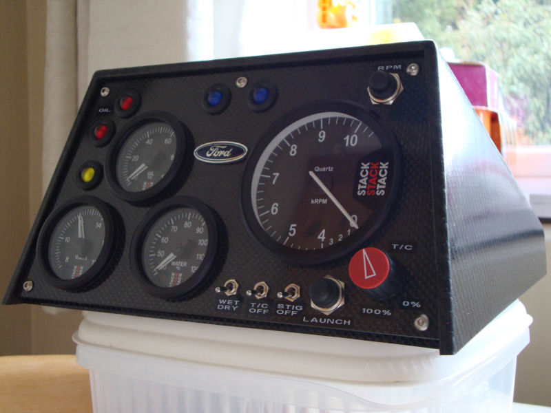
I also sourced some carbon panel, 1.8mm thick, from Ledon Racing Services, and I've fitted the panel to the top of box, using the switches hold the panel in place.
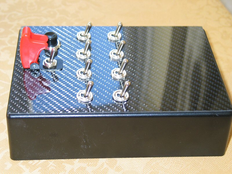
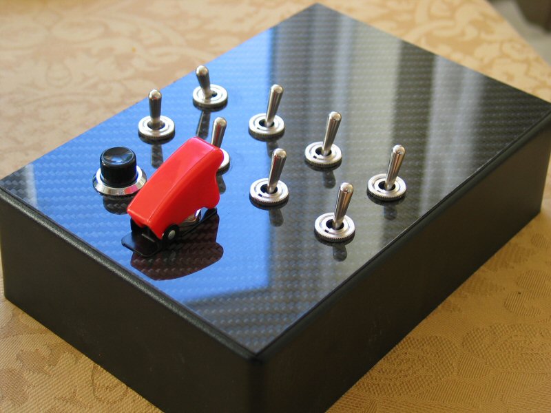


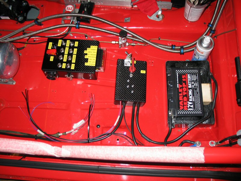
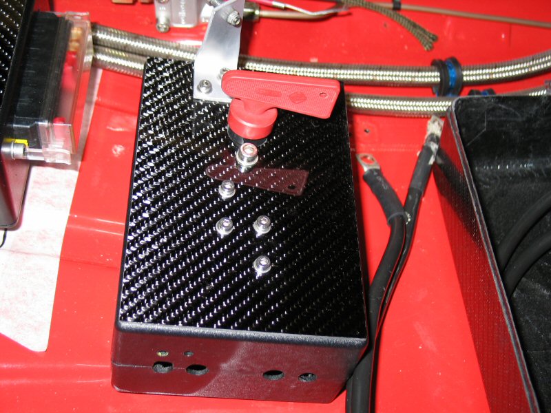
I've also covered the box that houses the isolator switch with 1.8mm thick carbon sheet.
I labelled up the dashboard and the control box using a Dymo Labelpoint 100 label printer, and a 45021 black on white 12mm label cartridge.
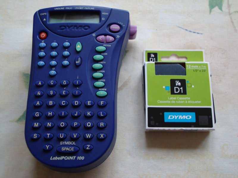
I had previously used yellow on black labels, but they didn't really have the professional look I was after.

Coil on Plug polarity
Pin 2, is the +12V feed, and Pin 1 goes to the relevant Coil connection on the ECU. Looking at the COP itself, the pins numbers are molded in to the COP casing, in very tiny writing, so identifying Pins 1 and 2 is straight forward.Injectors
The Fiesta ST150 fuel injectors in the Duratec head are fine for around 160BHP. So you will need to replace the in-head injectors with either Bosch or Weber injectors. I use uprated Bosch injectors as they flow enough fuel for the BHP figures I'm aiming for.Note: Dont forget that if you want to run the Duratec in sequential injection mode, that each injector must be capable of delivering the fuel required for each cylinder. If you run the injectors in batch mode instead, so that they fire in pairs (in what is also called wasted spark configuration) then the injectors only need to delivery half the amount of fuel, as they in effect fire twice per cycle.
The stock air and water temperature sensors both need replacing with items intended for the DTA ECU. The water temp sensor in the alloy sensor housing on the end of the head, is for the temperature display on the Fiesta dashboard, and not intended for use with the ECU. Therefore it needs to be swapped for an ECU sensor. The standard temperature sensor has a M12x1.5 thread, so you'll need to get an M12x1.5 to 1/8NPT thread adaptor to allow it to be replaced. Burtons sell these adaptors for around £5 each plus Postage and Packing. Simply unscrew the standard sensor, fit the adaptor, then screw the new sensor inside the adaptor. Use thread sealent to ensure that there are no leaks when the engine is up to temperature.
You must get the RP5110-130 sensor, as it has a slot machined in the end of the input shaft to ensure an 'interference fit' with the Titans. I previously bought an RP5130-130 in error (looks just like the one shown in the picture) and this didn't fit as the input shaft was too small for the Titans. You have been warned....
Sensor polarity
The two pin sensors on the engine (Water temp, Air temp, and both of the magnetic Crank and Cam sensors), are wired as follows:Sensor signal return wire to Pin 1, and Sensor Ground wire to Pin 2. Pins 1 and 2 are marked on the connector bodies(in very small raised print)