Fuel Injection - Page 1
LastNote: May 2010 - this page was written back when I was running the Zetec 2.0 (1998-2008). I've now changed to Duratec 2.0 and Titan roller barrels, and the Vehicle Electrics page features information pertaining to the Titans. When the installation is complete, I'll re-write this page. Most of what you read below is still relevant to both engines, but I'll add more detail on the Titans over the coming months.
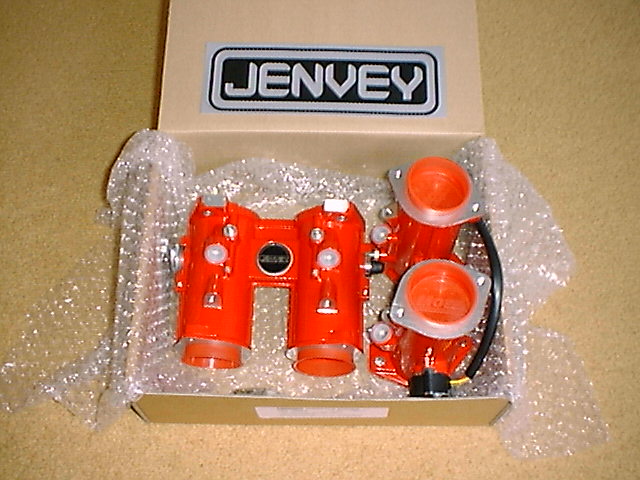
I've been using Jenvey Fuel Injection throttle bodies since the car was first running, because I wanted to squeeze every last drop of horse power from the 2.0 Zetec. And when you look in to the costs of fitting the engine with a carburation system, the Injection route isn't that much more expensive than the side draught Weber route, once you've bought the manifold, filters, Ignition system (Black-Box), linkages, and of course the carburetors themselves. You don't need such a sophisticated Ignition System to manage carburetors (and therefore as expensive), but you still need something capable of producing a 3D ignition map. Some people have modifed the Zetec engine to accept a distributor, which is driven off the end of one of the camshafts. It looks quite odd, but the conversion is supposed to work quite well.
This page explains how the Zetec injection system comes together, what you get when you buy throttle bodies, and how to get the most from the system.
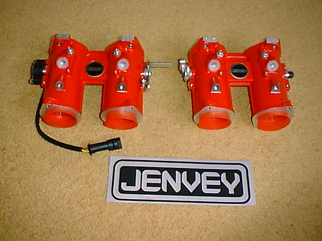
The model of throttle bodies that I used on the Zetec were the Jenvey TBP45i. They had a 45mm bore, which is the optimum size for the 2.0 engine. You can fit bodies with larger or smaller bore's, but thats down to the state of tune of the engine. Talk to your supplier and listen carefully to their advice. Biggest isn't necessarily the best when it comes to throttle bodies.
So what do you actually need, to make throttle bodies work?

What else will I need?
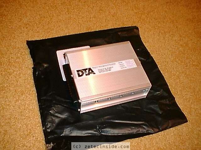
An Electronic Control Unit (ECU)
The ECU controls the injectors, and the ignition system. An ECU consists of a microprocessor which, using a 3D ignition and a 3D fuel map, reads information from sensors on the engine, and determines the amount of fuel the engine requires, and the right time to fire the spark plugs to ignite the mixture in the combustion chambers.In 2001, the ECU I chose back then for the Zetec was the DTA-Fast E48-EXP. It was packed full of excellent features, and proved 100% reliable. It also has a data capture facility, which was useful after completing a run, as I could see from the logs, where I could try a bit harder.
My DTA Map
I first had Zetec engine tuned in 2002, by Owen Developments. They gave good power figures at the time (~180 BHP) and the map seemed OK, but over the years I've gradually tweaked the settings here and there, partly to try to make the car more driveable (round the paddock etc). The most recent modification was to cure the cold starting problems which have plagued me for years. In 2006 I solved this with the help of Ash Mason's DTA map (Ash won the Midland Speed championship in 2005 and runs a Red top Vauxhall 2.0 in his Westfield). I've changed the Air temperature compensation, Water temperature compensation, and Startup enrichment maps, as per the images below, and the engine now starts on the first push of the starter button, even after it has been left standing for a week!Below are the settings which cured the cold start problems.
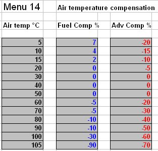 |
Air temperature compensation map |
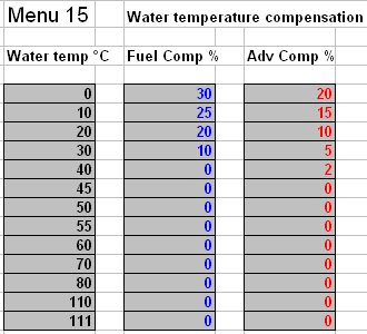 |
Water temperature compensation map |
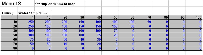 |
Startup enrichment map |