Life F88R
This information has been gathered during my ownership of the Mygale EcoBoost, which came with an F88R ECU. This is a non-GDI ECU, but it was fitted with the necessary electronics to drive GDI (Gasoline Direct Injection). All the EcoBoost Formula Fords were fitted with the same type of Life ECU. The Life ECU offers comprehensive levels of protection, which was required to prevent teams from altering the power outputs of their cars. As a consequence, the ECU is fairly well locked down, with just simple diagnostics and data logging available to teams.For the 2016 season, I ran with the base 170BHP map, which was replaced in August 2016 with the Ford 200BHP map (Life connected to my car at home, using Teamviewer and loaded a different calibration on to the ECU), and during the year, I still struggled with lack of power compared to others in the class. That situation would soon change.
At the end of October 2016, I started modifications to the car, which would see a significant weight reduction, the fitment of an engine driven alternator, a more powerful Turbo Technics S242 Revo turbo, plus the addition of a Syvecs X10 expansion module. The X10 module, provides an additional 10 input and 10 output channels, and is designed and built by Life, but marketed by both Life and Syvecs as their own X10 module. They can be bought for around £500 second hand, which is how I bought mine. The reason for fitting the X10 is to allow two rear wheel speed sensors to be fitted for launch and traction control, calibration switches for engine power, traction and launch settings, and a pair of steering wheel mounted paddle switches for pneumatic gear changes. The X10's outputs are used to control the two pneumatic valves which required for making the gear changes.
Wiring Diagram
One of the biggest challenges for anyone with a Formula Ford EcoBoost, was the lack of a wiring diagram. Ford refused to release the diagram, as its considered their Intellectual Property (IP). So armed with a spare wiring loom, a voltmeter, some measurement probes and a few hours of spare time over Christmas, I produced my own diagram, which incorporates all the engine and chassis connections.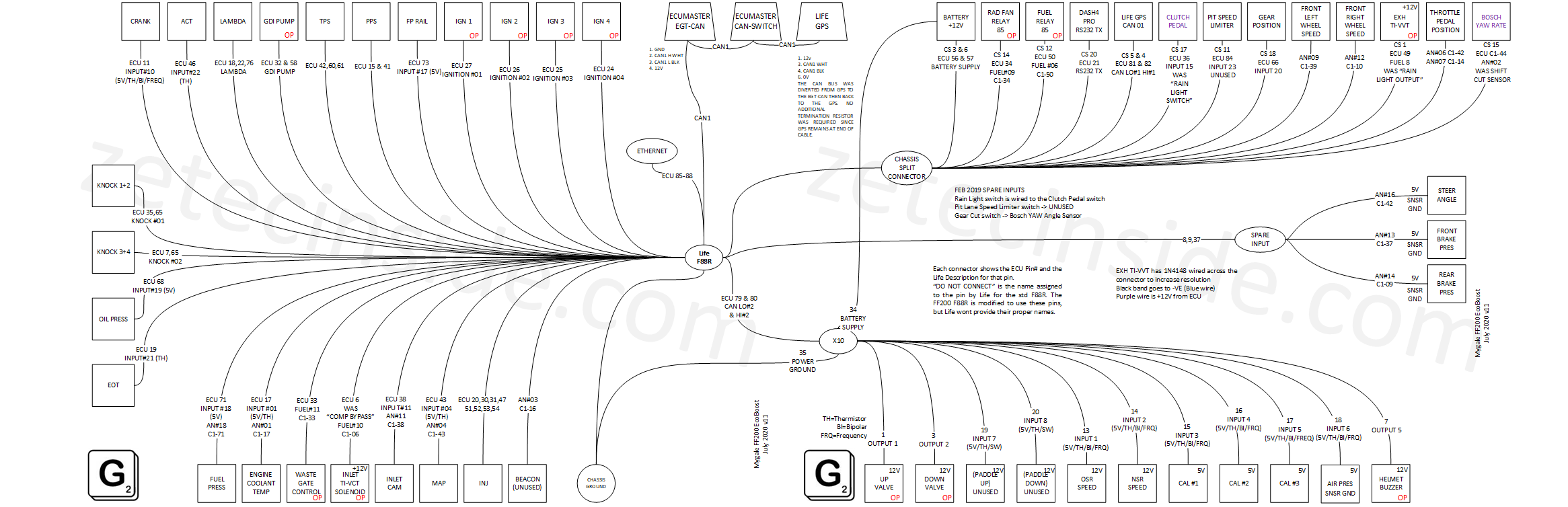
 This is also available in PDF format (v10)
Also I've shown all of the connections, and the pinouts of not only the ECU and chassis split connector, but also the connectors used on the engine wiring loom and the chassis loom.
This is also available in PDF format (v10)
Also I've shown all of the connections, and the pinouts of not only the ECU and chassis split connector, but also the connectors used on the engine wiring loom and the chassis loom.
Connecting in the Syvecs X10 expansion module
You will need to connect the X10 module not only to a suitably fused 12V power connection, but also more importantly, to the ECU CAN #2 HI (pin 80) and CAN #2 LO (pin 79) signals. The ECU CAN #2 wasnt used on the standard EcoBoost cars. It is therefore free for you to connect to the X10 module. CAN #2 is a highspeed CAN bus, dedicated entirely to the X10. The ECU also has a CAN #1 bus, and this on most cars, is used to interface the ECU to the Life 10Hz GPS module, which sits forward of the driver, usually above the steering column.To gain access to the two CAN #2 pins on the Life ECU connector, you must take the Life 'hairdryer' 88-way connector apart, and fit two wires.
Note: There is no termination resistor required for CAN #2. This is a dedicated high speed CAN bus, reserved for the X10 module, and not meant for connection to other CAN type devices. Therefore the F88R and the X10 already have their termination resistors built in. Therefore do not add a termination resistor to either end of the connection as this will lead to errors.
Parts required for the X10 loom
The X10 connector is made by TE Connectivity, and can be bought from RSWWW.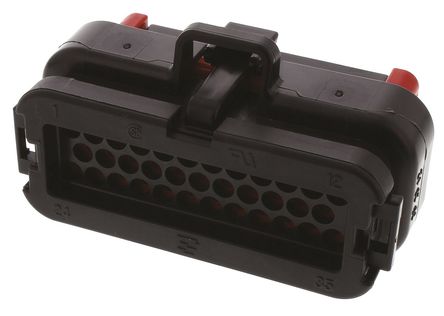
Part number http://uk.rs-online.com/web/p/automotive-connectors/6809437
As can the TE crimp pins for the X10 connector.
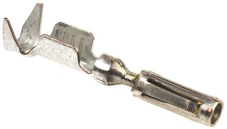
Part number http://uk.rs-online.com/web/p/pcb-connector-contacts/7181507
Parts for the F88R - X10 loom
The crimp pins for the F88R come in two different sizes, depending on the position of the pin inside the connector.These are the larger, higher current connectors.
Junior Timer crimp receptacle,15-20 AWG
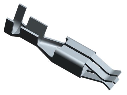
Part number http://uk.rs-online.com/web/p/automotive-connector-accessories/9097583
These are the lower current connectors mostly used for inputs to the F88R.
Contact female 0.3-0.75mm² Micro-Timer I
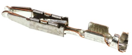
Part number http://uk.rs-online.com/web/p/pcb-connector-contacts/7180850
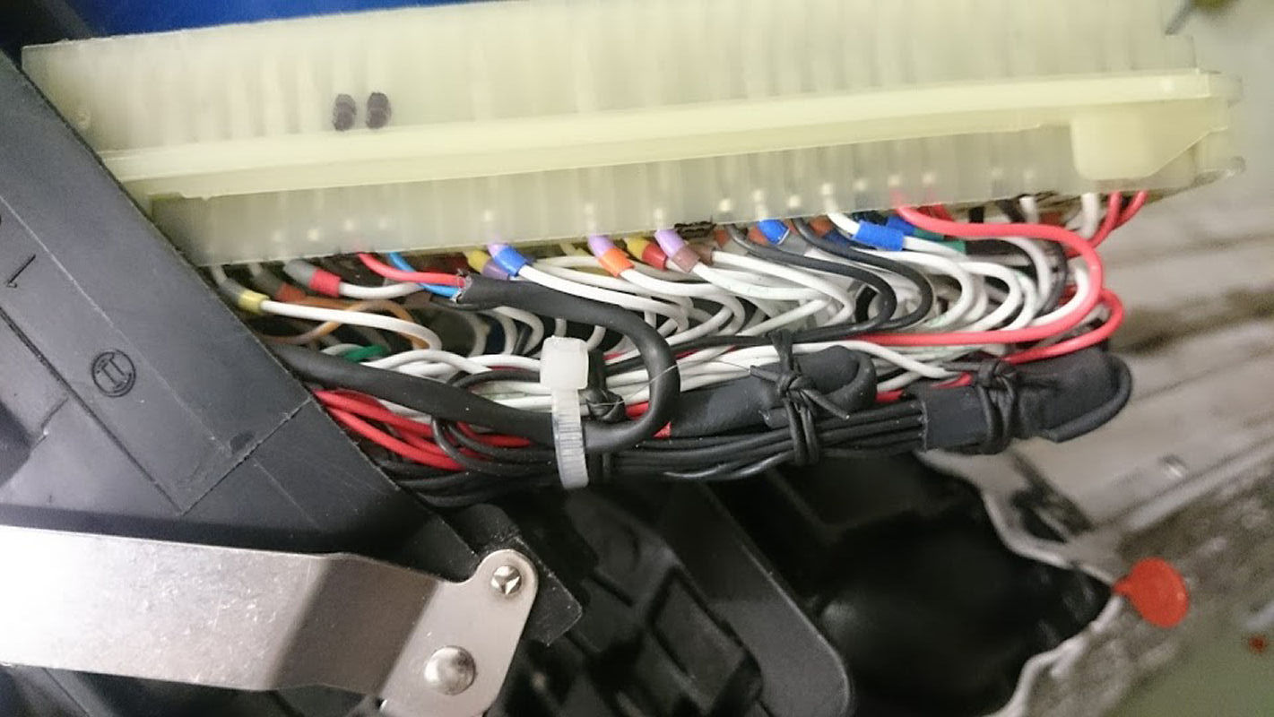
Adding wires to the F88R ECU 'hairdryer' connector
Since only two wires are needed to interface the X10 module to the F88R ECU, I used a twisted shielded cable. The benefit of using shielded cable is to further protect the CAN #2 signal from interference. Of course, the shield needs to be earthed, but thats no big deal.The pinouts for the X10 Module are here.
Start by cutting and removing the heatshrink cover from the back shell
Next undo the small screw from the end of the connector that holds the connector inside the shell. Do not lose the screw, it is an unusual thread.
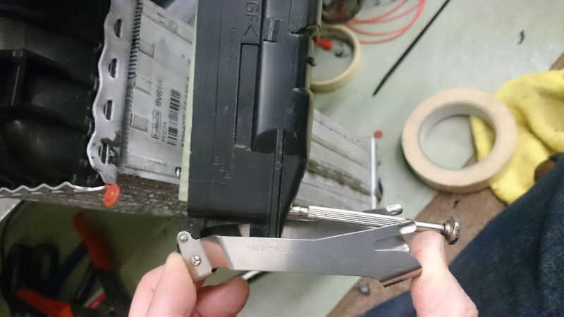
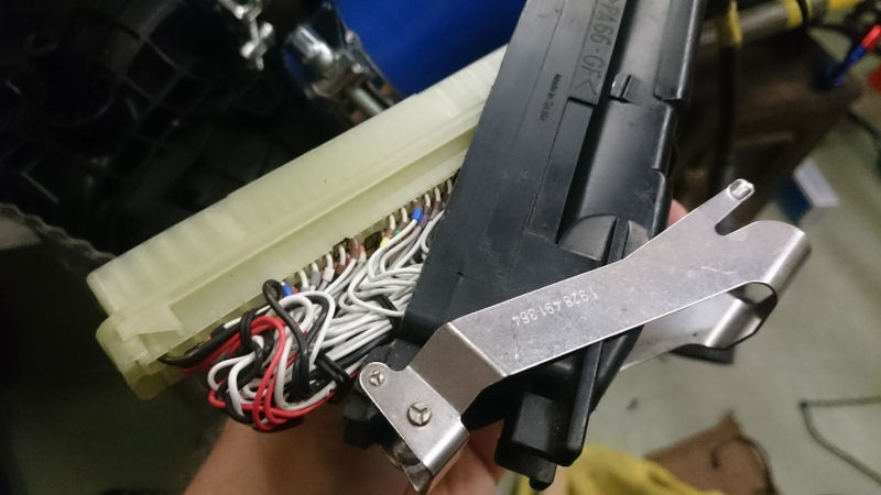
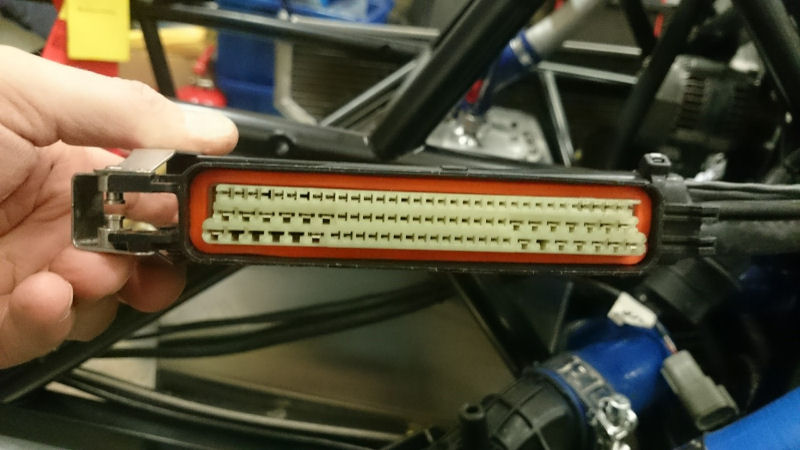
With the screw and the heatshrink removed, push the cable in to the backshell and at the same time carefully pull/ease the connector out. Be very careful not to damage the mass of wires that are inside the backshell. They are tied together in bundles, but you still need to take care.
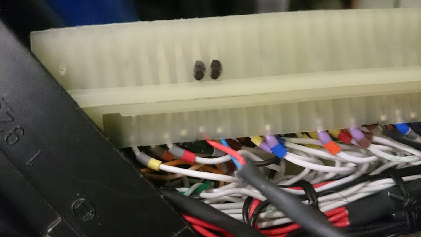
Feed your wires through the backshell, and in to position. Mark the connector with a marker pen if you like, to identify which holes the pins are going to be inserted in to. For CAN #2 you will need to use pins 79 and 80.
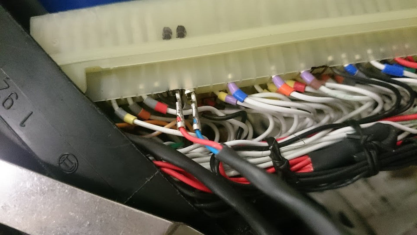
The crimps can be pushed in to the connector, until you feel a positive click.
Cable tie or use lacing chord to fasten the new cable to the rest of the cables inside the back shell.
Carefully feed the connector back inside the back shell, whilst pulling the cables back out the rear of the shell. Once the connector has gone back in to its position, you can replace the fixing screw removed earlier, and then cable tie the rear of the shell to make sure that it stays together. Ideally, you would replace the heatshrink removed at the start of the process, with a new piece.
Adding calibration switches
In order to control the boost (4 stages) and launch and traction control, we must add several rotary switches to the X10. These need to produce unique voltages for each switch position, and the simplest way to do that is to use a resistor ladder.Simply, a chain or ladder of resistors is soldered in series, to the connections on the rear of the rotary switches, and the switch is also provided with 5V and 0V. As the rotary switch is turned, the number of combined resistors in the ladder changes, and the voltage returned is proportional to the switch position. The ECU is taught the voltage for each switch position and these are saved in the ECU's Calibration.
I've used 12 position Grayhill switches, and miniature 470R 0.25W resistors, wired in to use the 5V Sensor and Sensor Ground connections from the X10. My three rotary switches are wired in to a Deutsch DTM 6 way connector, and this allows the easy removal of the switch panel. The cable from the X10 to the switch panel connector actually contains 8 wires, only 6 are used by the switch panel, and the two spares are diverted to the steering wheel for the paddle switches (together with 12V and 0V so in total four wires go to the steering wheel via a red Binder connector. The two paddle inputs on the X10 are configured for Switch mode, which is why the paddles use 12V shared from the X10 power rail. It wouldnt make sense to use the 5V regulated sensor supply from the X10, to provide power to the paddle switches, as the switches might cause interference on the 5V rail when operated).
So six of the eight wires in the 8 way cable go to the 6 way connector for the switch panel. Only five of the six wires are needed (5V, 0V, Inputs 1,2,3) but I've left a spare Input wire which might be handy in the future if I need to add an additional switch.
Wiring the calibration switches
I soldered a chain of 470R 0.25W resistors (CFR16J470R from RS) to the Grayhill rotary switches (56SD30-01-1-AJS/440-7685 from RS), and connected Sensor 5V to pin 12, and 0V to pin 1, and the output is taken from the centre connection of the switch.
Rear wheel speed sensors
The sensors used on the car are part number XS608B1NAL2/198-554, from RS. They have an amber LED in the end where the wire exits the barrel, and the LED illuminates as the heads of the metal bolts pass the sensor, which is great for diagnostics.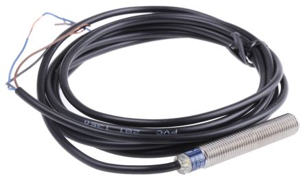
Helmet buzzer
I've used one of the free outputs, pin 7 aka output 5, from the X10 to connect to a Piezo buzzer which is powered off 12V. The buzzer is placed inside my crash helmet. The ECU is programmed to make an audible warning when the optimum gear change RPM is reached. This is far easier to listen out for, than looking for shiftlights on the dashboard. It works really well, but the piezo buzzer has to be placed directly over the ear, or it just cannot be heard over the noise of the engine.February 2017 Upate
My car was tuned in February 2017, and we tested and calibrated all of three rotary switches that I made. They all have the end-stop set to prevent the switch from going from position 12 to 1, so in order to select 12, I have to turn the switches clockwise a full rotation.The CAL switch was setup for four positions that I can use. The 1 O'Clock position, Map 1, gives me 313BHP and position 4, Map 4, gives me around 100BHP less. This is essential for wet weather conditions.
The Launch switch has 12 positions, and 1 through 11 are used to set the launch RPM. Switch position 1 is for 3000rpm, 2 is for 3250, 3 is for 3500 etc. If I give the throttle more than 60% when in first gear, with the speed < 2MPH, launch mode is selected. The ECU only opens the throttle around 16% whilst it holds the engine revs at the set engine RPM. I then dump the clutch and keep the throttle nailed, and the ECU limits wheel spin as the car accelerates. Once 40MPH is reached (in first usually) the launch mode is transferred to Traction Control, and I just go up through the box and accelerate as normal. If I put Launch switch in to position 12, it turns off Launch altogether.
Traction control on the third rotary switch, works in a similar way. I have 11 switch positions to select from, and each one alters the strategy that the ECU uses for Traction control. If I turn the traction switch to position 12, then traction is turned off completely.
July 2018
The car was tuned again to see if we could squeeze more power from the EcoBoost on 102 octane race fuel. The results were a very big increase in torque, with more than 300ft.lb across the entire rev range, and over 320bhp, again, an increase from the 313bhp I'd had since February 2017. Driving the car with the extra power at Lydden Hill the following weekend, it felt simply ballistic in a straight line, so much so I was concerned that the brakes were going to be up to slowing the car down. I soon got used to it, and started to short shift instead of reving the engine, which made better use of all the low down torque. It was just a shame the clowns that tuned the car, sabotaged my efforts by 'forgetting' to turn Launch Control back on, so my starts at Lydden were all slower than the sister car. Of course, with the ECU locked, I had no access to turn LC back on again. This required a further visit from the tuner to re-enable LC.December 2018
Following a long campaign by myself, Ford finally agreed in August 2018 that our Life ECU's could be PARTIALLY unlocked. Only the paid-for features, not the full map, but that was still better than what we had access to previously, and would allow us to make changes to L/C, T/C, and a host of other settings including VVT. My ECU went back to Life in October 2018, and in December it was ready. It took 10 weeks as the ECU had a battery charging fault whereby the CMOS battery kept going flat, and it needed some internal circuitry mods to cure that problem.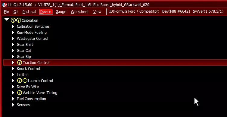
February 2020
Following yet more negotiations, Ford gave me permission to have the ECU fully unlocked, and after paying Life £540 for future support, they made a remote connection to the ECU and fully unlocked it. This gives me 100% access to the ECU, and the very first task was to reprogram it to allow the ECUMaster EGT-CAN adaptor datastream to be read, and that was a lot easier than I expected.
March 2020
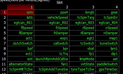
I took the unlocked car down to Devil Developments, for a tune. On their dyno the car was suffering from wheel spin. So in the afternoon I had to pack the car back on the trailer and head over to SRD Tuning at Haywards Heath where we extracted 375bhp and 405ft/lb using 102 octane fuel.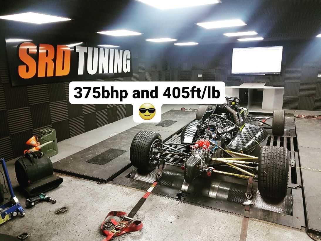
March 2021
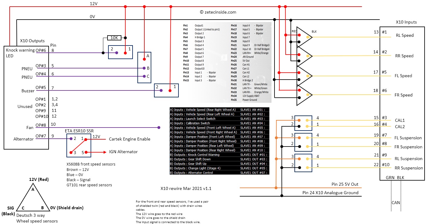
I rewired the Syvecs X10 expander, so the 10 inputs are now all used. I have moved the front wheel speed sensors from the ECU on to the X10, so it now provides the speeds of all four wheels to the ECU over CAN. This does mean that there is no filtering or raw data from the sensors, but the rears worked OK so adding the fronts to the X10 shouldnt be a problem. I've also wired in four suspension potentiometers so I can measure the ride height of the car, and the final two inputs are for the CAL and Launch Control switches on the switch panel down by my left leg.I've wired in a blue Knock LED, which is set to illuminate only if a Knock Event is raised. The remaining X10 outputs used are for the gear change warning buzzer in my helmet, an alternator control solid state relay, which allows the ECU to turn off the alternator when certain conditions are met. And of course the pneumatic paddle shift solenoids remain under X10 control.
Freeing up the two front wheel speed sensors from the ECU, allowed me to wire in the exhaust camshaft sensor using one of the pair of free frequency inputs, so the ECU now has full control of both inlet and exhaust VVT solenoids, and therefore can control the timing of both camshafts for the first time. (Make sure you get the polarity right for the actuator solenoid, or the ECU can't be expected to control the cam timing! Been there, done that)
Finally, using the spare "Beacon" input, I've wired in a NTC temperature sensor, which is assigned as Ambient Air Temperature, and is situated in the airbox. And I've connected a Reveltronics K-Type thermocouple amplifier, to AN#03, which is assigned to Exhaust Gas Temperature, so the ECU now has the aggregated post-turbo temperature to monitor. This is especially useful for keeping the Anti-lag working at safe levels.
The Racetechnology RS232 DASH4PRO has been swapped for a CAN BUS version, and I've repogrammed the ECU datastream to send 48 messages, which provides far more useful information on the dashboard than I had before with the FF RS232 link.
Click the diagram for a larger version.
May 2021
The first outing of the car with the CAN BUS connected Race-technology DASH4PRO, and it worked perfectly, as did the X10 expander with the new wiring loom. The only gremlin was one of the front wheel speed sensors went intermittent, which was caused by the proximity of the sensor to the disk. I refitted one of the original 8 hole Mygale sensor disks, and that cured the issue. This gives me a better solution. I now have an 8 hole and a 16 hole disk on the front axle, so I've got the increased resolution, and a second opinion should the first disk have any issues. Both the rear wheel speed sensors worked 100% of the time, using the reluctance rings I manufactured last year. For the next event in June, I have made changes to further improve the launch and traction control settings. Analysis of the data from the 9 launches at the first Blyton event show that the launch control isnt producing 10% wheel spin all of the time. So the S curve has been made more aggressive, as well as the cutoff speed for launch control being reduced from 40 to 30mph, handing over to traction control at 30.1 mph. I am still running reduced boost (-500mBar) in first gear, and -200mbar in 2nd, which is protecting the Hewland gearbox from the otherwise 400lbft of torque produced by the EcoBoost engine. I've also reworked the traction control, which still needs some fine tuning.Spin Target table using Yaw angles
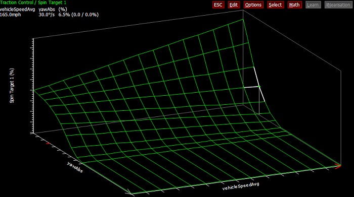
June 2021
I ran a 0 to 60 in under 2.9s at Pembrey, using the new launch settings. Thats not bad, and there is still room for improvement. It does very much rely on the surface, and Pembrey has a concrete apron which we start from, and the tarmac is also very abrasive.I've added a further output to the X10, making six in total. The X10 is now controlling the up and down pneumatic actuators, the helmet buzzer, knock warning light, the alternator, and a new sixth item, more of which will be revealed in time.
October 2021
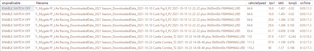
More changes to the traction control finally saw me get in to the 2.1's for the 64ft at Castle Combe, on the coolest day we've raced all year. I'll make further changes in March 2022 for the return and the start of the season.November 2021 Engine Health Monitoring
I've exported all of 2021's eighty three log files captured from the ECU, in to CSV format, and imported them all in to SQL Server Express. This gives me approx 320,000 rows of data, which I can now analyse. The intention is to use machine learning, to try and indicate potential issues with the engine, such as oil pressure deviations, temperature changes etc. I've already used the data to highlight an issue with the Engine Enable signal, which is a logic signal that the ECU is looking for to turn the fuel and ignition on/off. During one of my runs at Castle Combe in October, the engine power suddenly dropped on a bend, and I found, looking through the data using LifeView, that the enable signal went low for 0.3s. I wrote a query in SQL to see if the issue had been seen previously, and sure enough, at Curborough a few weeks earlier, the exact same issue had caused another loss of power, briefly. I remember the sensation of power loss when driving at Curborough, but at the time I didnt find the cause. From the analysis, I've now replaced the igntion switch, and insulated the terminals on the back of it, just in case the switch was touching the chassis tube that its positioned next to.