
DTA S80Pro ECU
Configuring and using the DTA S80Pro DTA Fast ECU
So what are the steps in getting the engine running for the first time? Once you've completed the wiring loom, and everything is connected, the first step to configure your DTA ECU, must be to install the Windows DTA ECU software. This software allows you to see the view that the S80 has of the engine's sensors. The software is free, and available for download from the DTA web site.
Installation is simple. Just run the Setup.exe once you downloaded it, and keep clicking on Next until it has finished. Your next task is to physically connect the ECU to the Windows Computer, or laptop. For this task you will need a 'serial' communications lead, available from DTA, which has a 15 pin D-Type connector on the ECU end of the cable, and a 9 pin D-Type serial connector on the PC end of the cable.
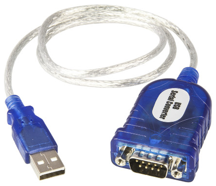
If your computer doesnt have a 9 pin D-Type serial connector, dont worry. You need to buy a USB-Serial adaptor, like the one above, and this will provide the interface connector required to connect the computer to the ECU.
Once the DTA software (and USB->Serial adaptor) is installed, you will need to connect the ECU to the PC using the DTA serial lead, and then you can to run the Windows DTA software, and connect to the ECU.
But before you can do that, you will need to find which COM port number the USB-Serial adaptor has created, as that will be asked for by the DTA software when you wish to access the ECU via the lead. Computers usually have one or two communication ports, aptly named COM1 and COM2. But when you fit a USB-Serial adaptor, the COM port number doesnt automatically follow on as COM3. You might find for instance that the COM port number is 9 (as in the example below), and the number isnt guaranteed to stay the same every time you plug the USB-Serial adaptor in. So to find out what number has been assigned, follow the step below.
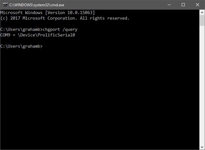
The easiest way to find out which COM port the USB-Serial lead is using, is to open a CMD prompt, and type in the following command.
chgport /query
This should show COM followed by a number, and in the example given, COM9 is being used. Make a note of the COM port number, and fire up the DTA software.
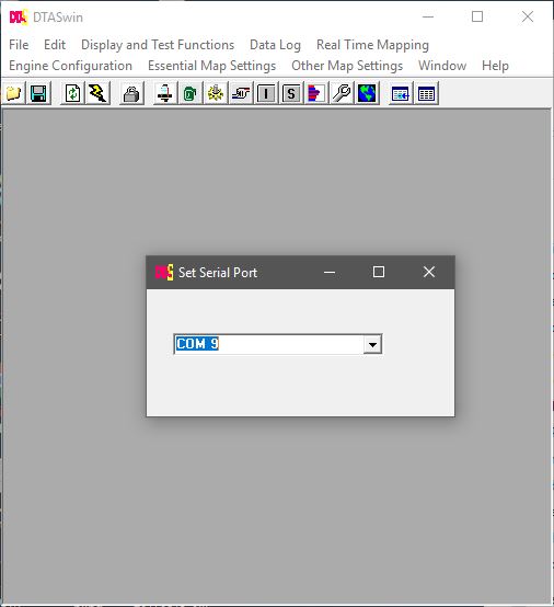
Now start the DTA software, and if the ECU isnt contactable, please select Work Offline, then select File, Serial Port options, and select the COM port from the list provided.
Make sure the ECU is powered up, select File, Connect to ECU. If all is well, the computer should now be able to communicate over the serial port you just chose.
Now you need to establish if there is a base map available for you to use.
If you have a Duratec-HE or Zetec engine, then use the 'Zetec without Map' map, as this will give a good basis for a successful map.
The Zetec and Duratec both use a 36 tooth timing wheel, with a single tooth missing, in other words, a 36-1 timing wheel.
This gives 10° of crankshaft rotation between each tooth (360° divided by 36 teeth = 10° rotation per tooth).
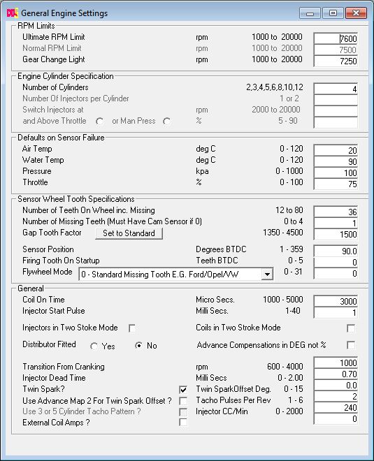
The General settings page will already show 36-1 if you have used the Zetec map.
The crank sensor position before top dead centre, is
90° for the Zetec, and 90° for the Duratec engines.
So make sure that you plug these figures in to the General settings page before trying to start the engine.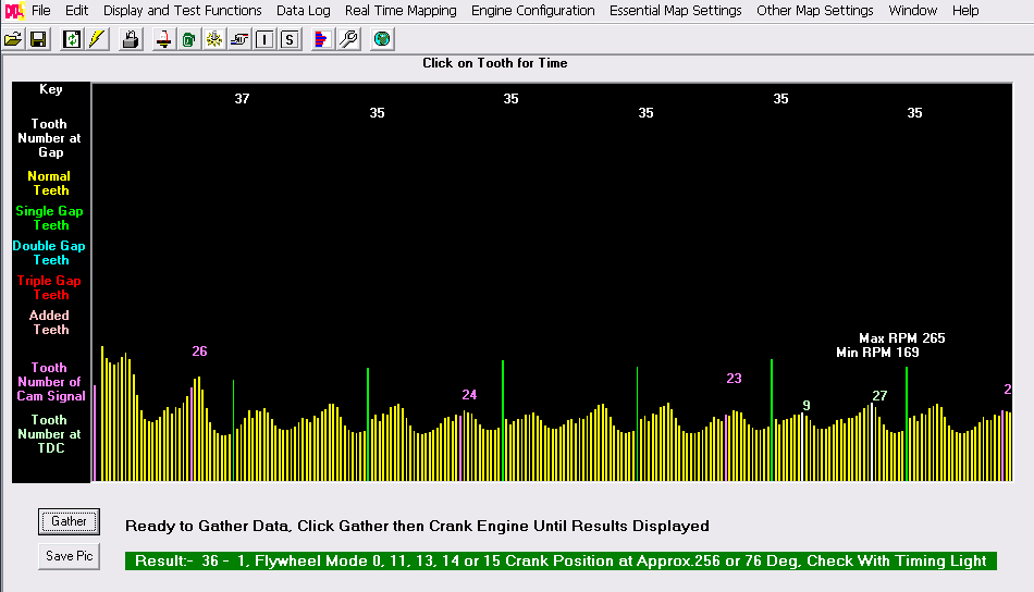
The reason for having the crank sensor sat 90° before TDC (BTDC) is to allow the ECU to advance and retard the igntion as required. Once the missing tooth has been detected by the ECU, it knows that in another 90° the piston will be at top dead centre. Therefore any time in the next 90° rotation, the ECU can fire the plugs or injectors, to ignite the mixture in the cylinder, or inject fuel in to the cylinder. So if the engine needs 30° advance, the ECU knows that in 6 pulses time (60°), the crank will be at 30° BTDC, and that the ECU can then fire the ignition to produce a spark at 30°
If the crank position sensor sat at 0° (TDC) then the ECU would never be able to provide advance ignition, as the event would have passed before the ECU could have any chance to do anything. So 90° is a good compromise that allows advance/retard to be automatically managed by the ECU.
The next thing to do is to turn on the Oscilloscope view, and crank the engine over with the ignition off. This will display a trace from the cam and crank sensors, and the program will establish the crank sensor BTDC position, and the effective crank timing tooth that the cam sensor is triggering on. Click Gather, and turn the engine over until the screen shows 100% complete. The pink numbers above the cam trace, are the ECU's interpretation of which crank tooth the Cam Timing has been triggered. The numbers should stay the same across the trace. On this trace it changes across the timeline, so in the ECU I have turned off Coil per Plug, and Sequential Injection, below 800rpm, so the engine will start more easily.
The settings on the screen are then plugged in to the General Settings page as below. You may notice that the Normal RPM Limit is grayed out (Shown beneath the Ultimate RPM Limit). This is because my map uses the Spark and Fuel cut patterns to reduce the engine horse power, prior to hitting the Ultimate and rather abrupt RPM Limit.
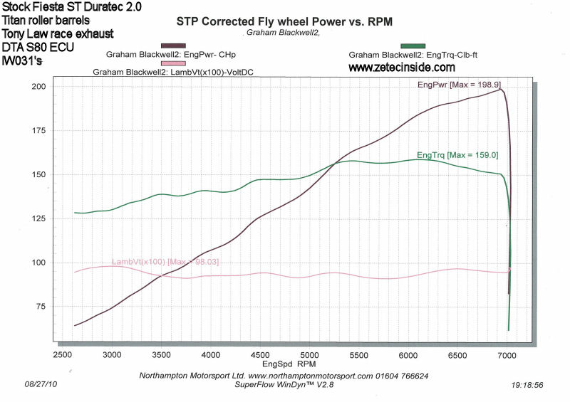
On Friday 27th August 2010 I took the Fiesta along to Northampton Motorsport for a dyno session, and we achieved 199bhp at 7000rpm, with much more to come.
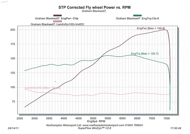
In June 2011, after curing an overheating issue and changing the driveshaft, the car went back to NHM for another couple of hours mapping.
We raised the red line to 7600rpm, and Troy managed to squeeze 200bhp out of the engine again, but this time extending peak power to 7600revs. The car is simply stunning to drive. It is well mannered at low revs, and pulls like a train in all gears.
Flashing the S80 firmware to the latest version
Every now and again, it is worth updating the firmware in the ECU - my 'how to' Youtube video shows you how to do thisIn April 2014 I updated the firmware in the DTA S80 from v63 to v71, and filmed a quick Youtube video showing the process.
DTA Launch Control
The S80 supports Launch Control, and in order for this to work, it has to be provided with the speed of one of the undriven rear wheels. Its only when you use Traction Control (which I also intend to do) that all four wheel speed sensors are used. I've wired in both the rear sensors, and have wiring available to connect the two front sensors.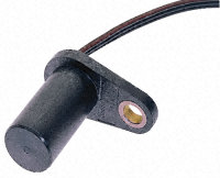 I've used the following 'GT1' hall effect gear tooth sensors, 4.5-24Vdc, from Radio Spares.
They're about £27.50 each.
I've fitted one on each rear wheel, attached to the hub using M6 threaded rod, with the face of the sensor pointing at the rear of the wheel studs (four studs in total).
I've used the following 'GT1' hall effect gear tooth sensors, 4.5-24Vdc, from Radio Spares.
They're about £27.50 each.
I've fitted one on each rear wheel, attached to the hub using M6 threaded rod, with the face of the sensor pointing at the rear of the wheel studs (four studs in total).
 This is one of the GT1 sensors, mounted on the Fiesta rear axle. It needs to be spaced as close as possible to the wheel studs without touching, to ensure a good signal to the ECU. I've used stainless M6 threaded rod and nyloc nuts to hold it all together. These are Ford Focus Mk1 stub axles, with FRP 10mm axle spacers.
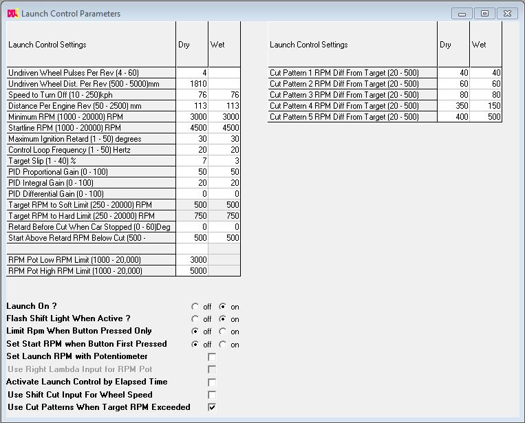 So the next step in getting L/C working is to connect the laptop up and make some setting changes in the ECU.
The screenshot shows my settings as programmed for 2014. Remember I've managed a 0-60 in just 5.23seconds, without L/C which I doubt L/C would better to be honest.
Launch control just takes the guess work out of getting the car moving. It cant give you more grip than you already have. It just makes the launch consistent.
So the next step in getting L/C working is to connect the laptop up and make some setting changes in the ECU.
The screenshot shows my settings as programmed for 2014. Remember I've managed a 0-60 in just 5.23seconds, without L/C which I doubt L/C would better to be honest.
Launch control just takes the guess work out of getting the car moving. It cant give you more grip than you already have. It just makes the launch consistent.
DTA Traction Control
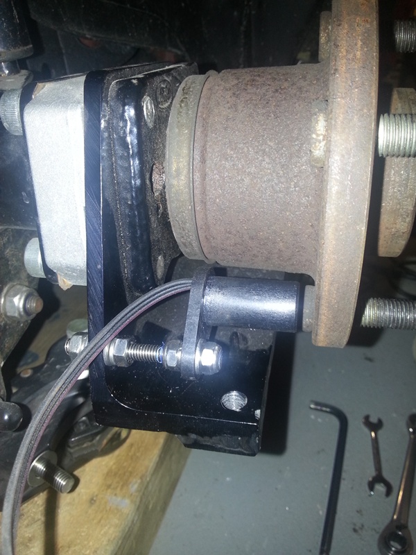
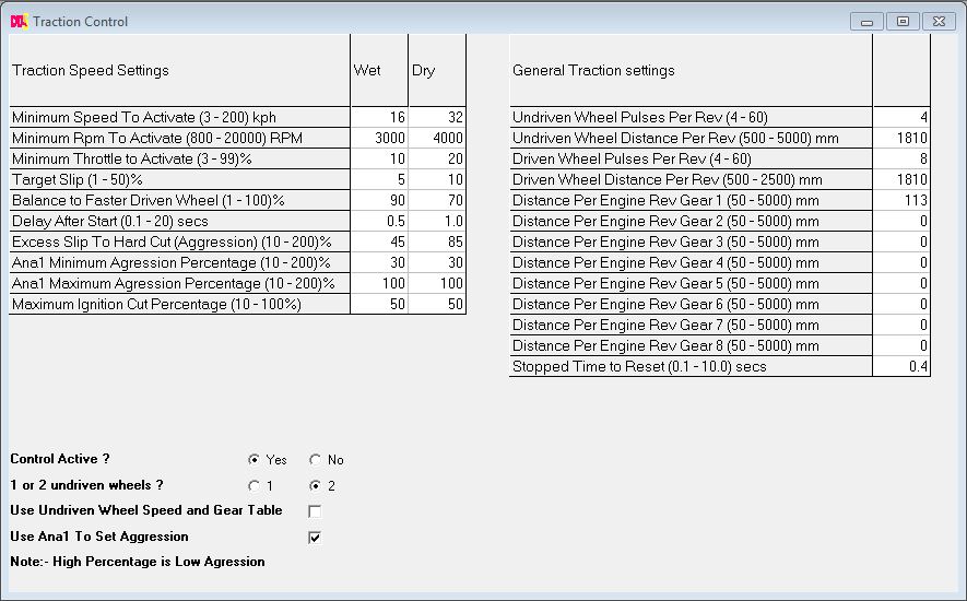
I've fitted a pair of GT1 sensors to the front wheels, using a set of eight equally spaced 13mm indentations drilled in to the rear face of the front disks. The sensors are held approx 1mm above the surface of the disks, using a pair of U channel aluminium brackets, fastened to the caliper brackets.The traction control settings are setup as follows:
DTA Spark and Fuel Cut Patterns
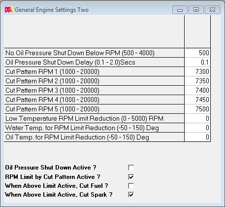
I've made some radical changes to the ECU Map, to swap over to the new Spark and Fuel Cut Patterns feature. This allows five patterns, which may be invoked prior to the hard rev cut being reached, and each pattern is programmable to reduce the power by a set percentage, using random spark and injection cutting. When used with Traction and Launch control, it gives a less harsh cut, which upsets the car's handling less. You need to enable the shift cut patterns in the General Engine Settings Two window. The patterns I've arrived at are as follows: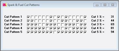
General Engine Settings Two window
DTA Flat shifts
From v63.0, the DTA firmware allows the ECU to monitor the gear position sensor in the gearbox (Analogue ch3), and simply cut or retard the ignition when it senses movement, allowing the next gear to be engaged without needing to lift off the throttle. The technique I have used, to change gear, is to pull back on the gear lever, and lift my foot from the throttle pedal just a fraction, which allows the next gear to be selected without the use of the clutch. After which point full throttle is re-applied. This is far better for the transmission than using the clutch.So how does Flat Shift work?
The ECU is connected to the selector barrel in the gearbox, via a rotary position sensor. The sensor converts rotation of the gear selector barrel, in to an analogue voltage, which the ECU needs, to determine that the gear lever is being pushed or pulled. To facilitate Flat Shifts, I have upgraded the sensor that came with the gearbox, to a dual channel hall effect sensor, as supplied by Neil at Geartronics.co.uk. This dual channel sensor shares the +5V supply from the geartronics gear position indicator, for power, and has two totally isolated outputs. One of the two outputs from the sensor, lets call it Channel 1, is fed back to the gear position indicator so you can continue to see which gear is selected. The other output (lets call it Channel 2) is connected to the DTA S80 ECU, to the Analogue 3 (Ana3) input.Here is a picture of a dual channel Penny and Giles hall-effect sensor. The black and white wires are the output from the 2nd channel. I have added a waterproof connector to this pair of wires, and have connected it back to the Ana3 connection on the back of the ECU. The white wire carries the output signal, and the black wire is the earth.

 So once the dual channel sensor is connected to the ECU, the DTASwin software is used to calibrate the ECU for flat shifts.
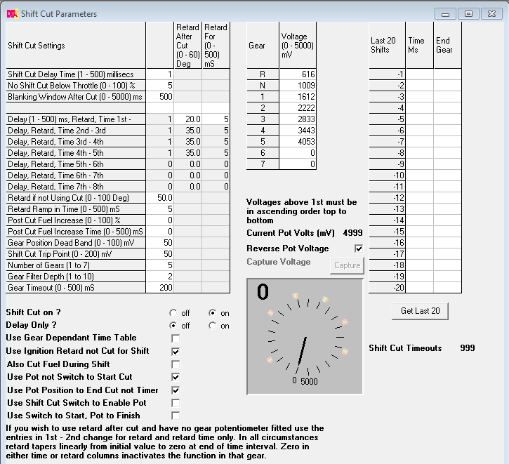
Here is a screen dump of the settings I have arrived at.
So once the dual channel sensor is connected to the ECU, the DTASwin software is used to calibrate the ECU for flat shifts.
Here is a screen dump of the settings I have arrived at.These are taken from the www.dtaforum.com discussions.
The settings shown on the screen are quite straight forward to arrive at. But fundementally, if you want flat shift to work, you must have Shift Cut ON, Delay Only OFF, and tick the two options "Use Pot not Switch to Start Cut" and "Use Pot Position to End Cut not Timer". This will ensure that the ECU is only using the rotary sensor to monitor gear shifts. What you also need to do, is Calibrate the ECU for the different voltages output for each gear position. During calibration, each gear must be selected in turn, click on the Capture button, and the voltages will be read saved in to the ECU. Once the voltages have all been read, and saved, when you next drive the car, with Shift Cut ON, you should be able to change gear without lifting off the throttle. Assuming you have a sequential gearbox of course.
Other settings
The 'gear position dead band' needs to be set so that when in the desired gear there is room for inaccuracies i.e. the pot will not always return to the same mV position. I suggest you take 10 readings of the mV up and down the gearbox for each gear and use the average for that gear.The shift cut trip point needs to be set high enough not to cause unintended initiations over bumps and the like and low enough to enable the linkage/drum to move no more than necessary to initiate a cut, start with say 20 mV and go up if you get unintentional cuts.
To start with you may wish to increase the 'gear timeout' up to say 500, you will be aware in the car if this is happening at this long time, it will feel like an age.
One thing to remember is that you must pull / push the lever through whilst the cut is happening.
Also make sure at idle your throttle sensor is at 0% otherwise you may get stalling whilst on the start line.
