Raspberry Pi Project Page
LastPi Zero G-Meter LED Display

This project page describes the accelerometer that I'm building, based on the Pi Zero, Allo mini-Rainbow RGB LED pHAT, and ADXL345 3-axis accelerometer. The purpose of the G-Meter is to help me maximise the speeds and the G-Forces in every corner. Using the LED matrix visual display, it will provide me with an indication of how much lateral (side to side) G force that the car is generating, with a target of 3G.
So how do we go about building a G-Meter?
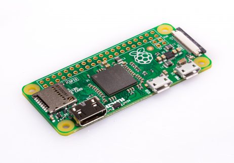
We need a Pi Zero, which is the smallest footprint Raspberry-Pi you can get. Its tiny, and has two micro USB ports, a micro HDMI port, a microSD card slot, and a ribbon connector to allow connection of a camera if required. Everything about the Pi Zero is micro, and the first challenge is attaching a keyboard, mouse and wifi dongle, when there is only one micro USB port free. One of the two micro USB ports is for the power supply to power the Pi, and you need to provide a 5V feed, with at least 700mA for the Pi to work. So in order to attach all the other the peripherals required to allow us to develop code on the Zero, we need a USB hub.
This is the Pi zero
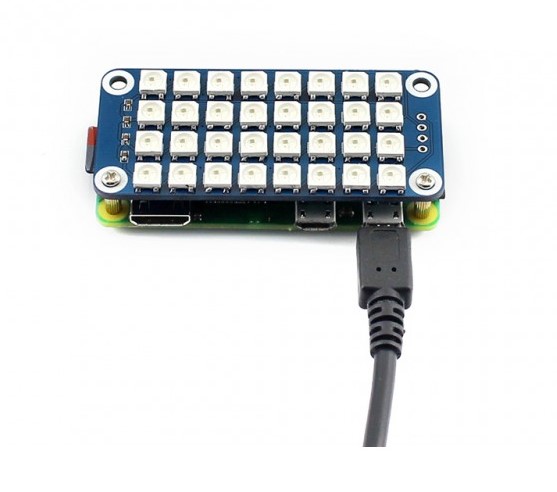
This is the pHAT fitted to the top of the Pi
Operating System
I've installed Raspbian Stretch Lite on to a 16GB MicroSD card, using Win32DiskImager, and the device quickly boots to the graphical interface. As the code is developed, the device will be set to boot to the Command Line Interface (CLI) as it doesnt need to be running the GUI for the Python code to execute. Booting to CLI also speeds up the boot time.The LED HAT is made by Allo, and their page can be found here https://www.allo.com/sparky/rainbow.html
The accelerometer is made by Analog Devices, and their page can be found here
I chose the following board from Modmypi, available here https://www.modmypi.com/raspberry-pi/sensors-1061/orientationaccelerometers-1067/adafruit-triple-axis-accelerometer-adxl345/?search=345
Programming the RGB LED pHAT
The fun part has been working out how to write to the pHAT. The RGB Matrix consists of 32 LEDs, which are arranged in a snake like way. With the address of the first pixel being 0, and 31 for the last, you'd think that the matrix would just run right to left, top to bottom. Wrong. Its right to left, but then the line drops down and runs left to right, then down, and right to left etc.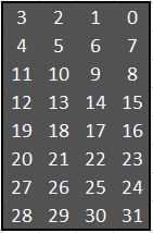
To switch on an LED on the pHAT, we use the following NeoPixel command from our Python program
strip.setPixelColor(x, Color(grn,red,blu))Where x is the LED number (refer above), and Color is the RGB color, but in GRB order (Dont ask me why)
Installing NeoPixel
To use the NeoPixel library, involved downloading and installing the zip file, which is available from https://github.com/jgarff/rpi_ws281x.Copy the ZIP file to the Pi, and run
unzip rpi_ws281x-master.zipInstall the depended-upon software
sudo apt-get install build-essential python-dev scons swigCompile the program
cd rpi_ws281x-master
sudo scons
Run the line below to perform testing. You can see the RGB LED flickering
sudo ./testRun the following line to install the python library
cd python
sudo python setup.py install
Run the demo code for testing
cd examples
sudo python lowlevel.py
SuperUser rights required
Note: You can only control the pHAT LEDs if the python program is run under the SuperUser context. In other words, if you try to run your Python code using the Python2 IDE, it will fail with an error as you dont have the rights required to access the pHAT. So to develop code, use the IDE, but to test the code, you need to have a command shell open, and run the code from the directory where the code sits, usingsudo python programname.py
Scrolling text
To scroll a message, or a bitmap, across the display, we need to define a viewport, of 4 columns wide by 8 rows tall, and move the viewport from left to right, across the block/bitmap.Say for example, I want the word Ready to move across the display.
In Python I have defined a block of 32 columns by 8 rows, and the 1's and 0's in the block, determine if the LEDs are on or off on the LED matrix. If you look at the example carefully, you'll see that it shows the word 'Ready'
row1="11110000000000000000010000000000"
row2="10001000000000000000010000000000"
row3="10001001110001100011010100010000"
row4="11111010001000010100110100010000"
row5="10100011111001110100010011110000"
row6="10010010000010010100010000010000"
row7="10001001110001110011110011110000"
row8="00000000000000000000000000000000"
Actually, as its not that easy to see the word Ready in the example, I'll replace the zero's with spaces, and then you'll see what I mean.
row1="1111                 1          "
row2="1   1                1          "
row3="1   1  111   11   11 1 1   1    "
row4="11111 1   1    1 1  11 1   1    "
row5="1 1   11111  111 1   1  1111    "
row6="1  1  1     1  1 1   1     1    "
row7="1   1  111   111  1111  1111    "
row8="                                "
If we take four characters from the first row, row1, and four characters from the second row, row2, and so on, and use the 1 or 0 to switch on or off the LEDs in their corresponding rows in the pHAT, it will make the majority of the letter 'R'.
1111
1
1
1111
1 1
1  1
1
We then move the view port to the right by one character, to take the four characters, starting from the 2nd character of row1, row2, etc.
111
   1
   1
1111
 1
  1
   1
And this is how we give the effect of scrolling text. There needs to be a delay between each transition, otherwise the bitmap would flash across the display so fast you wouldnt be able to read it. I've chosen 0.065seconds at present, and this gives a nice smooth scroll, but not too fast to make the text unreadable. The bitmap can of course be any length, I've just chosen 32 columns as an example.
When we write the bitmap to the screen, we have the ability to choose individual pixel colours, but for simplicity, I just choose a single color, and all the LEDs then use that. Here is the code I wrote to scroll the bitmap across the 4x8 matrix.
def scroller():
	sDelay = 0.065
	for k in range(0,32):
		for i in range (0,4): #3210 (3=lhs 0 being top right)
			if row1[k+i]=="1": #if its a 1, turn on the LED
				strip.setPixelColor(3-i, Color(grn,red,blu)) #GRB
			else: #if its not a 1, turn the LED off
				strip.setPixelColor(3-i, Color(0,0,0)) #GRB Blank
		for i in range (0,4): #4567 (4=lhs 7=rhs)
			if row2[k+i]=="1":
				strip.setPixelColor(4+i, Color(grn,red,blu)) #GRB
			else:
				strip.setPixelColor(4+i, Color(0,0,0)) #GRB Blank
		for i in range (0,4): #11,10,9,8 (11=lhs 8=rhs)
			if row3[k+i]=="1":
				strip.setPixelColor(11-i, Color(grn,red,blu)) #GRB
			else:
				strip.setPixelColor(11-i, Color(0,0,0)) #GRB Blank
		for i in range (0,4): #12,13,14,15 (12=rhs 15=lhs)
			if row4[k+i]=="1":
				strip.setPixelColor(12+i, Color(grn,red,blu)) #GRB
			else:
				strip.setPixelColor(12+i, Color(0,0,0)) #GRB Blank
		for i in range (0,4): #19,18,17,16
			if row5[k+i]=="1":
				strip.setPixelColor(19-i, Color(grn,red,blu)) #GRB
			else:
				strip.setPixelColor(19-i, Color(0,0,0)) #GRB Blank
		for i in range (0,4):#20,21,22,23
			if row6[k+i]=="1":
				strip.setPixelColor(20+i, Color(grn,red,blu)) #GRB
			else:
				strip.setPixelColor(20+i, Color(0,0,0)) #GRB Blank
		for i in range (0,4):
			if row7[k+i]=="1":
				strip.setPixelColor(27-i, Color(grn,red,blu)) #GRB
			else:
				strip.setPixelColor(27-i, Color(0,0,0)) #GRB Blank
		for i in range (0,4):
			if row8[k+i]=="1":
				strip.setPixelColor(28+i, Color(grn,red,blu)) #GRB
			else:
				strip.setPixelColor(28+i, Color(0,0,0)) #GRB Blank
		strip.show()
		time.sleep(sDelay)

#this is the main code to be run
#define the bitmap for the image 'Ready'
row1="11110000000000000000010000000000"
row2="10001000000000000000010000000000"
row3="10001001110001100011010100010000"
row4="11111010001000010100110100010000"
row5="10100011111001110100010011110000"
row6="10010010000010010100010000010000"
row7="10001001110001110011110011110000"
row8="00000000000000000000000000000000"
row1="0000"+row1 #prefix each row with four blanks, to smoothly scroll the bitmap on to the pHAT
row2="0000"+row2
row3="0000"+row3
row4="0000"+row4
row5="0000"+row5
row6="0000"+row6
row7="0000"+row7
row8="0000"+row8
red=0
grn=255
blu=0
#call the scroller routine
scroller()
ADXL345 3-axis accelerometer
Using the following library https://github.com/adafruit/Adafruit_Python_ADXL345To install the library from source (recommended) run the following commands on a Raspberry Pi or other Debian-based OS system:
sudo apt-get install git build-essential python-dev
cd ~
git clone https://github.com/adafruit/Adafruit_Python_ADXL345.git
cd Adafruit_Python_ADXL345
sudo python setup.py install
The ADXL board is addressed using I2C, and just needs four wires to work on the Pi.
The Pi Zero DIL header, provides the power, and data lines that the ADXL345 needs, on pins 1,2,4 and 6. But the pHAT already occupies the pins that we need to utilise for the ADXL, so my solution is to use a 40 way male to female ribbon cable, with an extra 40 way male IDC connector located midway along the cable. I can then plug the pHAT in to the male end of the cable, and I can use jumper wires to attach the ADXL using the middle male connector.
Once the library is installed, it is imported in to the Python code using the following example.
#!/usr/bin/env python2
# Author: Graham Blackwell
#
print "Loading libraries"
import Adafruit_ADXL345
print "Done"

# Create an ADXL345 instance.
accel = Adafruit_ADXL345.ADXL345()
accel.set_range(Adafruit_ADXL345.ADXL345_RANGE_4_G)
accel.set_data_rate(Adafruit_ADXL345.ADXL345_DATARATE_12_5_HZ)

x, y, z = accel.read()
xoffset = x
yoffset = y
zoffset = z

while True:
    x, y, z = accel.read()
    latG = abs((y - yoffset) * .0078125) #y is latG

    print "latG=%6.2fg" % (latG)
To convert the acceleration values returned from the ADXL345 in to G-Force, you first of all need to zero the three x,y,z channels, by recording the values returned whilst the board is stationery, and these are then subtracted from all subsequent readings. Once you've done that, all further values returned are multipled by 0.00390625, to convert the velocity in m/s2, in to G force.This article https://morf.lv/mems-part-1-guide-to-using-accelerometer-adxl345 explains about the conversion from m/s2 to G-force.
Finished product
Here is an animation of the finished product. I'm very pleased with it, I will be running it on the car at Pembrey for the first time in June.