
Adding the ECU Master CAN switch board V3
My car has three calibration switches which are used to select the calibration map, launch rpm and traction control settings. These are all wired in to the X10 expander, in three analogue inputs. They all work fine, but I wanted to move the switches on to the steering wheel, to allow me to safely make changes whilst driving. So I could just extend the analogue wiring to the steering wheel, but there is a better solution.
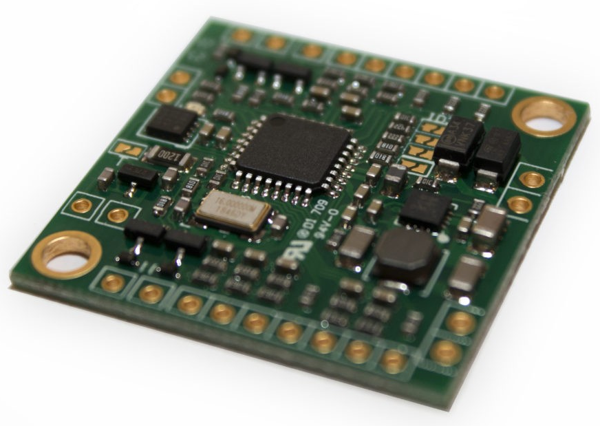
Polish company ECU Master produce a CAN Switch board, which provides 8 analogue inputs, 8 digital inputs, and four digital outputs. The board is designed to be affixed to a steering wheel, and the wiring between the board and the ECU is simplified since it only needs 12V, 0V and CAN Hi and Lo.
Setting up the CAN Switch board
Connect the Switch board to the Life ECU's CAN1 bus.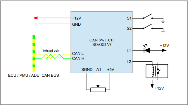
The Switch board box transmits three frames, on to the 1Mbps CAN BUS. Each frame is 8 bytes in size. Each frame has a hexadecimal address which identifies the frame to the ECU. For the Switch board on my car, the first frame has an address of 640h, and the second frame 641h, and the third frame 642h. We are using Receive A frames. Receive A frames consist of four 16-bit signed quantities sent high byte first. The Switch board is already setup to send High byte first.
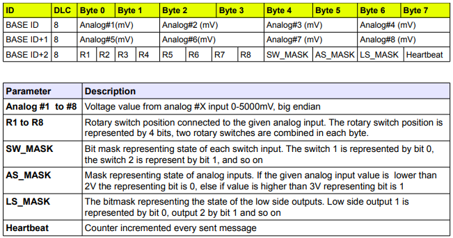
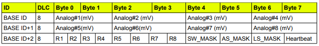
Msg1 with an ID of 640h, consists of 8 bytes; the first pair of bytes (16 bits in total) are for Analogue channel #1, the second pair of bytes are for channel #2, then channel #3 and finally channel #4.
Msg2 with an ID of 641h, consists of 8 bytes; the first pair of bytes (16 bits in total) are for Analogue channel #5, the second pair of bytes are for channel #6, then channel #7 and finally channel #8.
Msg3 with an ID of 642h, consists of 8 bytes; the first pair of bytes (16 bits in total) are for the rotary switch positions 1 to 4, the second pair of bytes are for rotary switch positions 5 to 8, then SW_MASK which represents the position of all 8 switches (each switch is represented by 1 bit) and AS_MASK which represents the state of the analogue inputs, then LS_MASK which represents the Low side outputs (8 bits) and the final byte which is a heartbeat counter which increments every time a message is sent.
Limitations
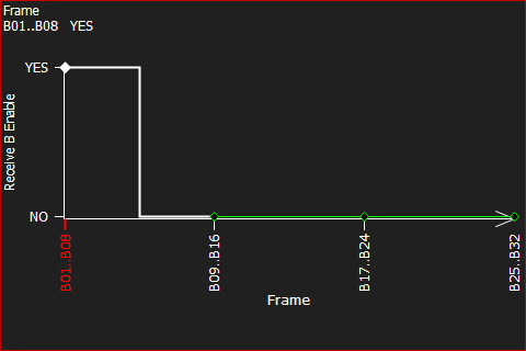
During testing it was apparent that the ECU wouldnt work with the data in A frame format (16bit). The rotary switch positions just couldnt be decoded, neither could the paddle switches. It couldnt differentiate the different switch positions in the pairs of bytes received. So I had to use to B frame format (8bit) for frame 642h, so the data was read as single bytes. Sadly this meant that only two out of the four rotary switches wired in to the SwitchBoard, could be read :(Setup the ECU to read the frames from the Switch board over CAN-BUS
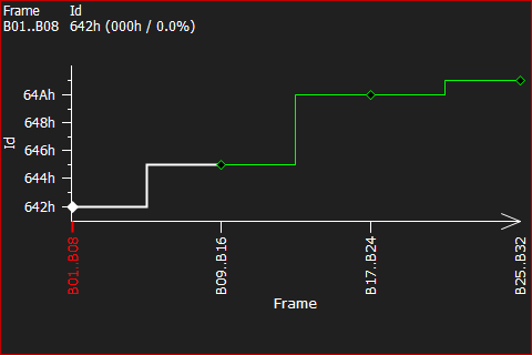
With the CAN Switch board connected to the two wire ECU CAN interface, run LifeCal and in Datastreams, configure the Generic CAN Receive as followsEnable the frame B01..B08 so it can be read by the ECU
I didnt have any B frame devices connected before I added the SwitchBoard, so I set the address for B01..B08 to 642h, as shown below:
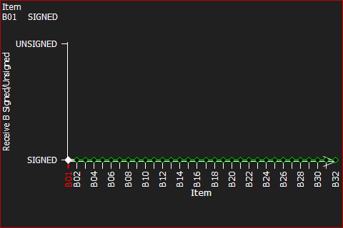
Make sure the frames are marked as Signed
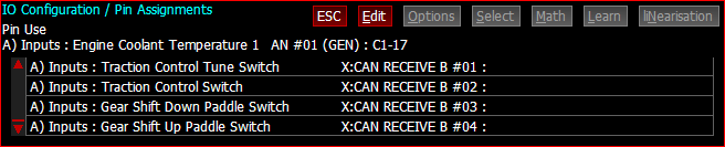
Now we need to go to the IO Config section in LifeCAL, to Pin Assignments and assign the data from the CAN Switch board.
Lets explain whats going on here.
This is the format of the data sent from the Switch Board. We are reading the third frame, which is the bottom row of the table above, BASE ID+2. I have assigned Byte 0 to Traction Control Tune Switch (X: CAN RECEIVE B #01) wire to analogue input #2. This frame should contain the two rotary switch values, R1 and R2. But because the LifeECU isnt capable of using the two 4 bit nibbles of the 8 bits sent in Byte 1, it cant be told that rotary switch position is the first nibble or the second nibble. Ideally I'd like to say to the ECU, in the first byte received (Byte 0), rotary switch 1 uses R1 and rotary switch 2 uses R2. But we cant do that. So we have to use the whole of byte 1 for rotary switch 1.
Note: I have wired rotary switch 1 to analogue #2 (R2), rotary switch 2 to analogue #4 (R4), paddle down switch to analogue #6 (R6) and paddle up switch to analogue #8 (R8).
If we do the same again, the second byte received (Byte 1), contains two rotary switch positions, R3 and R4, but again, we cant differentiate between the two. So we use the Byte 1 value for rotary switch 2 (X:CAN RECEIVE B #02) wire to analogue input #4.
So we're two rotary switches down and its not getting any better. Read on...
I've two switches, for paddle up and paddle down. If we look at Byte 4, that returns 8 bits which represent the switch positions of up to 8 switches. Guess what? Yes, the Life ECU cant use that data either since it has no concept of bit masks. So I've had to wire the paddle down switch to R6 (analogue input #6), so that the whole of Byte 2, represents the paddle switch (X:CAN RECEIVE B #03). And for paddle up, I've had to wire the switch to R8 (analogue input #8), so the whole of Byte 3 represents the paddle switch (X:CAN RECEIVE B #04). And we then ignore Byte 4,5,6,7 as we're not using any of those.
I had to program the Switch Board, to return the values that the ECU wanted to see. What I mean is, the values returned for R2 and R4, which represent the switch positions of the rotary switches, had to be values 1 to 12 for the eleven positions. By default the Switch Board returns 1 to 12,
2022: I am told that upgrading the LifeECU firmware does finally provide support for C frames. If I were able to do that, then Byte 4 (SW_MASK) should be accessible, and I could rewire the Switch Board to place the paddle up and paddle down switches on the switch inputs. That would allow me to add rotary switches for Launch and Calibration to R5 and R7, since the paddle switches would have been moved. As it is, the Switch Board device can only be used with 4 inputs, which is a real shame.
